The Basic Rules
1. Never work alone.
At least two adults must be in the shop when power tools are being used.
2. Never work when you are impaired.
This includes when you are too tired, stressed or hurried to work carefully.
3. If you cannot do a job safely in this shop, don’t do it.
There are limits to what we can build here.
4. Always wear closed-toe shoes in the shop.
Tools, chips and fixtures are sharp, and often hot. Shoes will help protect your feet from
injury. Leather shoes are preferred when welding.
5. Eye protection is essential. Always wear safety glasses when working or cleaning
tools.
Prescription glasses sold in the US with plastic lenses meet ANSI Standard Z87.1 for
safety.
6. Remove or secure anything that might get caught in moving machinery.
Rings, necklaces, long hair and loose clothes that get caught in tools can drag you along.
7. Keep your hands away from sharp tools.
Make sure that nothing that you do will cause you to be cut.
8. Dust, chemicals and smoke can be dangerous – work in well-ventilated areas,
minimize contamination and use appropriate protective equipment.
The safety equipment cabinet is on the patio.
9. If you’re unsure about the safe operation of a tool or any aspect of a job – ask for
help!
Have shop staff check you out on a tool the first time you use one with which
you are unfamiliar.
10. Clean up after yourself.
Before you leave the shop each day all tools must be returned to the toolbox, the machine
cleaned and wiped down and the floor swept. Leave 10-15 minutes for cleanup.
Drill Press Safety Guidelines
1. Run drill at correct RPM for diameter of drill bit and material. Ask shop personnel for the
correct RPM.
2. Always hold work in a vise or clamp to the drill table.
3. Use a correctly ground drill bit for the material being drilled. Shop personnel can help
select the correct bit.
4. Use the proper cutting fluid for the material being drilled. Ask the shop staff about the
appropriate fluid for the material you are machining.
5. Remove chips with a brush, never by hand.
6. Ease up on drilling pressure as the drill starts to break through the bottom of the material.
7. Don't use a dull or cracked drill. Inspect the drill before using.
8. Don't drill with too much pressure.
9. Always try to support part on parallels or a backing board when drilling thru material.
10. Never place taper shank tools such as large diameter drills or tapered shank reamers in a
drill chuck. Only straight shank tools such as standard drills can be clamped in chucks.
11. Always clean drill shank and/or drill sleeve, and, spindle hole before mounting.
12. Remove taper shank tools from spindle or sleeve with a drill drift and hammer.
13. Never try to loosen the drill chuck while the power is on.
14. Lower the drill spindle close to the table when releasing the drill chuck or taper shank
drill to reduce the chance of damage should they fall onto the table.
15. Never clean a machine while it is in motion!!
16. If the drill binds in a hole, stop the machine and turn the spindle backwards by hand to
release the bit.
17. When drilling a deep hole withdraw the drill bit frequently to clear chips and
lubricate the bit.
18. Always remove the drill chuck key, or, the drill drift from the spindle immediately after
using it.
19. Wear safety eye protection while drilling.
20. Let the spindle stop of its own accord after turning the power off. Never try to stop the
spindle with your hand.
21. Plexiglass and other brittle plastics can be difficult to drill. Ask the shop superintendent
for advice on drill and coolant selection when drilling these materials.
Lathe Safety Guidelines
1. Make sure that the chuck, driveplate, or, faceplate is securely tightened onto the lathe
spindle.
2. When removing the chuck, driveplate, or faceplate do not use machine power.
3. When installing the chuck, driveplate, or faceplate do not use machine power.
4. Move the tool bit a safe distance from the collet or chuck when inserting or removing
work.
5. Don't run the machine faster than the proper cutting speed – consult a speed and feed
table to determine the best speed.
6. In setting up the tool holder place it to the left side of the compound slide to prevent the
compound slide from running into the chuck or spindle attachments.
7. Always clamp the toolbit as short as possible in the toolholder to prevent it from breaking
or chattering.
8. Always make sure that the toolbit is sharp and has the proper clearance. Ask for
assistance making adjustments.
9. If any filing is done on work revolving in the lathe, file left handed to prevent slipping
into the chuck. Never use a file without a handle.
10. If work is turned between centers, make sure that proper adjustment is made between
centers and that the tailstock is locked in place.
11. If work is being turned between centers and expands due to heat generated from cutting,
readjust centers to avoid excessive friction.
12. Do not grasp or touch chips or turnings with your fingers, but get rid of them using a
blunt instrument. It is safer to turn off the lathe before clearing chips then to leave it
running.
13. Set the toolbit on the centerline of your work to prevent work from climbing over tool or
cutting above center and dragging.
14. Don't cut work completely through when turning between centers.
15. Remove chuck key from chuck immediately after using.
16. Turn chuck or faceplate through by hand before turning on the power to be sure there is
no binding or clearance problem.
17. Stop the machine before taking measurements.
18. Before cleaning the lathe remove tools from the tool post and tailstock.
Milling Machine Safety Guidelines
1. Work must be clamped securely in a vise and vise clamped tightly to the table, or, work
must be clamped securely to the table.
2. Do not take climb milling cuts on the shop’s mills unless instructed to do so.
3. Make sure cutter is rotating in the proper direction before cutting material.
4. Before running machine the spindle should be rotated by hand to make sure it is clear for
cutting.
5. Make sure the power is off before changing cutters.
6. Always use the proper cutting fluid for the material being cut.
7. Never run the machine faster than the correct cutting speed.
8. Make sure that the machine is fully stopped before taking any measurements.
9. Always use cutters which are sharp and in good condition.
10. Don't place anything on the milling machine table such as wrenches, hammers, or tools.
11. Always stay at the machine while it is running.
12. Don't take too heavy a cut or use too rapid a feed.
13. Remove the collet tightening wrench immediately after using it.
14. If at all feasible rig a guard or shield to prevent chips from hitting other people.
15. Use the milling machine spindle brake to stop the spindle after the power has been turned
off.
16. Before cleaning the mill remove cutting tools from the spindle to avoid cutting yourself.
Band Saw Safety Guidelines
1. The upper guide and guard should be set as close to the work as possible, at least within
1/4 inch.
2. If the band breaks, immediately shut off the power and stand clear until the machine has
stopped.
3. Examine blade before installing to see if it is cracked, do not install a cracked blade.
4. Use the proper pitch blade for the thickness of the material to be cut. There should be at
least 2 teeth in the material when cutting aluminum, and three teeth when cutting steel.
5. Check the speed table for the material that you are cutting. Do not run the band saw
too fast or the blade will wear out quickly.
6. If the saw stalls in a cut, turn the power off and reverse the blade by hand to free it.
25 Desember 2012
21 Desember 2012
Guidelines For Gas Metal Arc Welding (GMAW)
Gas Metal Arc Welding (GMAW) is a welding process which joins metals by heating the metals to their melting point
with an electric arc. The arc is between a continuous, consumable electrode wire and the metal being welded. The
arc is shielded from contaminants in the atmosphere by a shielding gas.
GMAW can be done in three different ways:
Semiautomatic Welding - equipment controls only the electrode wire feeding. Movement of welding gun is controlled by hand. This may be called hand-held welding.
Machine Welding - uses a gun that is connected to a manipulator of some kind (not hand-held). An operator has to constantly set and adjust controls that move the manipulator.
Automatic Welding - uses equipment which welds without the constant adjusting of controls by a welder or operator. On some equipment, automatic sensing devices control the correct gun alignment in a weld joint. Basic equipment for a typical GMAW semiautomatic setup: Welding Power Source - provides welding power. Wire Feeders (Constant Speed And Voltage-Sensing) - controls supply of wire to welding gun. Constant Speed Feeder - Used only with a constant voltage (CV) power source. This type of feeder has a control cable that will connect to the power source. The control cable supplies power to the feeder and allows the capability of remote voltage control with certain power source/feeder combinations. The wire feed speed (WFS) is set on the feeder and will always be constant for a given preset value. Voltage-Sensing Feeder - Can be used with either a constant voltage (CV) or constant current (CC) - direct current (DC) power source. This type of feeder is powered off of the arc voltage and does not have a control cord. When set to (CV), the feeder is similar to a constant speed feeder. When set to (CC), the wire feed speed depends on the voltage present. The feeder changes the wire feed speed as the voltage changes. A voltage sensing feeder does not have the capability of remote voltage control. Supply of Electrode Wire. Welding Gun - delivers electrode wire and shielding gas to the weld puddle. Shielding Gas Cylinder - provides a supply of shielding gas to the arc.
1 Constant Voltage (CV)
Welding Power Source
2 Contactor Control/Power Cord
3 Weld Cable To Feeder
4 Ground Cable To Workpiece
5 Workpiece
6 Welding Gun
7 Constant Speed Wire Feeder
8 Electrode Wire
9 Gas Hose
10 Shielding Gas Cylinder
13 Mei 2012
AutoCAD® 2010 Tutorial - "Creating a Surface of Irregular Shape"
.....sambungan
6. In the command prompt area, the message “Specify
fourth point or [invisible]
face>:” is displayed. Pick the corner below the last
selected corner as shown.

8. In the Visual Styles toolbar, click on the 3D Hidden icon
to display the model with hidden lines removed. Note that
the edges of the polygons are displayed as shown.
9. On your own, examine
the model by selecting
the different Visual
Styles.
10. Rest the Visual Styles toolbar to 2D
Wireframe, the default AutoCAD display
mode.
Using the Invisible Edge Option
• The Invisible Edge option is used to turn off the display of selected edges and
therefore allow the adjacent polygons, created by the 3D Face command, to
appear as being joined together.


6. In the command prompt area, the message “Specify
fourth point or [invisible]
face>:” is displayed. Pick the corner below the last
selected corner as shown.
7. On your own, repeat the zigzagging
pattern to define polygons until all
corners of the inclined surface have been
selected and additional polygons are
created as shown in the figure. Note that
the last polygon we created is a threesided
polygon.
8. In the Visual Styles toolbar, click on the 3D Hidden icon
to display the model with hidden lines removed. Note that
the edges of the polygons are displayed as shown.
9. On your own, examine
the model by selecting
the different Visual
Styles.
10. Rest the Visual Styles toolbar to 2D
Wireframe, the default AutoCAD display
mode.
Using the Invisible Edge Option
• The Invisible Edge option is used to turn off the display of selected edges and
therefore allow the adjacent polygons, created by the 3D Face command, to
appear as being joined together.
10 Mei 2012
PROACTIVE MAINTENANCE
Abstract:
Toyota as an automotive market leader in Indonesia with 30% market share, always strives to do Kaizen “continuous improvement” on each of their activity. One of the realization kaizen in manufacturing side which becomes Proactive Maintenance Method to make no breakdown machine on production time is zero breakdown activity. This activity is nearly based on TPM concepts but many modification strategies have conduct to reach its goal. First thing that revolutionary is Mieruka concept, how to know the process and machine problem using coverless strategy.
To get commitment from production side who become the owner of machine, PM-Production Maintenance which emphasized on qualified production member knowledge transfer to others and SM-Self Maintenance which move to find the root cause of problem both productions, maintenance and engineering, also present. Senmonginou (Special skill Training) is a method to fulfill maintenance & production skill to solve machine fault and abnormality.
Others new strategies that become proactive maintenance method will described clearly in this paper. Examples of implementation programs in TMMIN (Toyota Motor Manufacturing Indonesia) will be presented.
Proactive Maintenance Concepts
Based on the first terminology of proactive maintenance, it is stated that proactive maintenance is a maintenance method that commissions corrective actions aimed at the sources of failure. It is proposed to extend the life of mechanical machinery as opposed to
1) making repairs when often nothing is broken,
2) accommodating failure as routine and normal, and
3) preempting crisis failure maintenance
But, when we generally discuss about proactive maintenance, broader aspect could be included just like when we have a program that assists in scheduling preventive maintenance at the recommended intervals and monitors when those tasks are performed, it becomes proactive. We are also proactive when we repair and replace components before they are getting failure. Training plant operators is also programmed to recognize components when they are showing signs of failure and having procedures to report those are also proactive2.
TPM as Windows to Reach Zero Breakdowns
One of the TPM (Total Productive Maintenance) objectives is reducing cost. An overall production cost, including how cost-saving happened by finding the root causes of machine worn out and failure then implement a precise countermeasure is also the proactive one. If we study in a short time to reach zero breakdowns, preventive maintenance cannot eliminate breakdown alone.
According to the principles of reliability engineering, the causes of equipment change with the passage of time refer to bathtub curve (figure 1) . The causes of early period failure are design and manufacturing errors. To combat them, the engineering design must conduct test runs at the earliest stage. Furthermore, maintainability improvement should be pursued to discover and treat weakness design and manufacturing. Accidental failures are caused primarily by operation errors, so the most effective countermeasure is to ensure that operators use equipment properly.
Wear-out failures are due to the limited natural life span of equipment parts. Equipment life can be extended by preventive maintenance and by maintainability improvement (through changes in design). This will reduce the wear-out failure rate.
Figure 1. Bathtub curve

Maintenance prevention is an effective countermeasure for all three types of breakdown. A maintenance-free equipment design must be incorporated at the planning/design stage to prevent early period, accidental, and wear-out failures.
Depicted on that illustration, preventive maintenance alone cannot eliminate breakdowns. All departments cooperated to do TPM, and maintenance as well as engineering and production must be involved in the breakdowns elimination. Based on effort to eliminate failures, it could be categorized into five countermeasures:
1. Maintaining well-regulated basic conditions (cleaning, lubricating, and tightening)
2. Adhering to proper operating procedures
3. Restoring deterioration
4. Improving weakness in design
5. Improving operation and maintenance skills
Figure 2 illustrates the relation between these five countermeasures. As this figure illustrates, breakdowns can be eliminated by carrying out simple procedures in a simple manner and its
aim to be zero breakdown. In another words, activity done to reach zero breakdown which involving all departments to gain no breakdown machine is derivative from TPM activity. And this activity also based on pillars of TPM which prior on jishu hozen or autonomous maintenance, kobetsu kaizen or conduct continuous improvement, planned maintenance, honshitsu hozen or quality maintenance and training maintenance which also motivate to bring strategic and systematic ways to step ahead towards breakdown elimination. This concept could be mathematic as:

......... Zero Breakdown Machine (second)…………. (eq.1)
It means that when TPM was running well with third stage implementation; preparation, implementation and stabilization on its company system especially on its maintenance side the ideal machine condition could be achieved. And the business supply chain also affected both on its upper and downstream.
On the next page, implementation of zero breakdowns activities in TMMIN (Toyota Motor Manufacturing Indonesia) will be described and illustrated, the method and sampling taken from its engine plant. We refer to TMMIN Ltd. Because this company has been applied the very well known methods: Total Productive Maintenance to achieve zero breakdowns in their plant. However, The TPM here is the unique one because they also implemented Kaizen and Mieruka system so we called it as “Proactive Maintenance”, a new approach to Maintenance Word Methods.
 |
| Figure 2. Relationships between breakdown countermeasures ........................... 01 ................................ |
9 Mei 2012
Inilah Konsep Sepeda Motor Listrik Masa Depan
KompasOtomotif - Kampanye kendaraan ramah lingkungan tidak hanya pada mobil saja, tetapi para produsen sepeda motor dunia juga sudah mulai menyiapkan konsep andalannya. Menariknya, sepeda motor bertenaga listrik ini, didesain dengan tingkat mobilitas dan kinerja tinggi di masa depan. Inilah desain sepeda motor listrik tersebut;
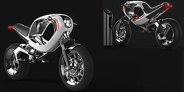


1. Frog eBike 2012 (Frog Design)
Frog eBike ini merupakan desain yang bertujuan untuk membunuh banyak desain tradisional dari bentuk sepeda motor konvesional. Motor listrik yang menggantikan mesin pembakarannya, dibuat seminimal mungkin dan merampingkan komposisi sepeda motor itu. Rumah baterai akan dipasang pada bagian bawah sasis dan posisi itu akan membantu menurunkan pusat gravitasi. Komponen lain yang akan dilengkapi pada Frog eBike ini termasuk panel instrumen OLED digital, kemudi fly-by-wire dan helm dengan pendeteksi retina, serta heads-up display.
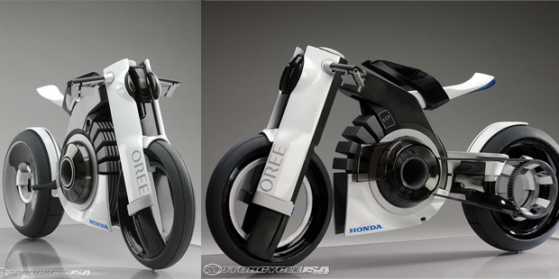
2. Honda Oree (Nike Albertus & Andre Look)
Inilah karya mahasiswa Jerman, Andre Look dan Nike Albertus. Sepeda motor ini paket baterai sport dan motor listrik, yang ditempatkan di tepi powerplant. Motor listrik tersebut dapat menyemburkan tenaga 91 PS dan torsi 169 Nm, sehingga kuda besi ini dapat berlari dengan kecepatan maksimal 190 kpj. Oree juga mengambil sedikit desain naked bike dengan suspensi yang terbuka.
3. AER Racing (Andre Federico Look)
AER akan menjadi salah satu konsep dengan tenaga besar, karena memakai 4 motor listrik bertenaga 143,5 kW. Pada roda depan dibekali satu mesin listrik kecil untuk menggunakan kembali energi yang ada saat pengereman. Lantas, 4 motor listrik yang masing-masing berbobot 4,5 kg akan dipakai untuk memberikan akselerasi lebih cepat.
4. BMW E 100R (Mika Mahonen)
Desain yang satu ini dirancang sebagai sepeda motor dengan nol emisi dengan biaya rendah. Karena itu, desain yang ditampilkan sederhana, mengandalkan rangka yang ringan dan mesin kuat. BMW E 100R mampu menghasilkan tenaga hingga 108 PS dan torsi 131 Nm, yang energinya disuplai oleh sebuah baterai pada rangkanya.
5. VertiGo (Maarten Timmer)
Desain sepeda motor listrik Timmer mengambil bentuk sport, yang menjanjikan torsi tinggi, akselerasi cepat, emisi rendah dan jarak berkendara 100 sampai 150 km. Memang secara desain VertiGo ini tidak jauh berbeda dengan motor sport konvensional, tapi dipercaya kuda besi ini dapat memberikan torsi instan.
Mesin Karburator VS Injeksi
Dikenal dengan teknologi Direct Fuel Injection, teknologi ini merupakan yang terbaru dalam hal pengkabutan BBM pada mesin bensin. Cara kerjanya juga serupa dengan mesin diesel, di mana bahan bakar diinjeksikan melalui jalur common rail langsung ke dalam silinder. Dan teknologi ini memang relatif lebih mahal dibanding sistem karburator.
Dengan penggunaan teknologi ini bahan bakar tentu lebih lebih efisien, output daya juga bisa jadi lebih tinggi dan yang terpenting emisi gas buangnya lebih rendah sehingga lingkungan lebih bersih.
Penggunaan bahan bakar dan timing injeksi bisa tepat dikendalikan sesuai dengan kondisi beban kendaraan. Kecepatan mesin ditentukan oleh waktu pengapian dan fungsionalitas injeksi bahan bakar dikontrol secara cermat oleh ECU (unit control mesin).
Teknologi injeksi juga ada yang bernama Port Fuel Injection, perangkat ini mungkin tipe yang paling umum dari sistem injeksi bahan bakar yang bisa ditemukan di seluruh dunia. Bahan Bakar disuntikkan pada setiap pengambilan port, biasanya terletak di kepala silinder dan intake manifold.
Desain yang melekat dari jenis sistem injeksi bahan bakar memungkinkan untuk lebih sedikit fleksibilitas dalam desain intake-manifold. Sehingga membuat pernafasan mesin membaik, dalam hal ini memungkinkan untuk modifikasi dengan perangkat turbo untuk menghasilkan tenaga lebih besar.
Teknologi injeksi selanjutnya ada Throttle Body Injection, di mana teknologi ini yang paling sering digunakan dalam desain untuk mesin karburator pada umumnya. Nosel injektor yang menyuntikkan bahan bakar berada di atas klep throttle. Campuran bahan bakar dan udara kemudian dibawa melalui saluran intake ke ruang pembakaran.
Sistem injeksi jenis ini ditemukan antara tahun 1980-1995. Keuntungan terbesar dari sistem ini adalah bahwa hal itu relatif rendah biaya dan banyak komponen pendukung seperti intake manifold, filter udara, dan saluran bahan bakar routing yang dapat digunakan kembali.
Jadi kesimpulan dari kedua teknologi ini adalah sistem injeksi lebih baik dari sistem karburator. Walau harga lebih mahal, teknologi ini memiliki masa depan yang lebih baik untuk lingkungan agar lebih hijau.
Apalagi mengingat kebijakan pemerintah mengenai pembatasan BBM subsidi, serta semakin banyaknya kendaraan terbaru bermunculan dengan teknologi mesin injeksi. Sudah selayaknya konsep pemahaman kita berubah tentang penggunaan bahan bakar yang tepat sesuai dengan perkembangan teknologi.
Sebab penggunaan teknologi injeksi pada suatu kendaraan itu diharapkan mampu menghasilkan pengkabutan bahan bakar lebih baik dari karburator dengan penggunaan BBM yang memiliki kadar timbal lebih sedikit atau memiliki nilai oktan lebih besar.
Jika pemahaman ini kita terapkan dengan baik, maka perawatan kendaraan injeksi jauh lebih mudah dan bisa jadi lebih murah dibanding kendaraan menggunakan karburator.
8 Mei 2012
jenis Kacang Terbaik Bagi Kesehatan
Ghiboo.com - Meskipun sering dituduh sebagai penyebab timbulnya jerawat, beberapa penelitian justru menunjukkan manfaat positif dari kacang-kacangan.
Berikut ini beberapa jenis kacang yang sebaiknya Anda mulai meliriknya beserta manfaatnya yang disadur melalui Women'shealth (27/4).
1. Almond (Porsi per 1 ons: 160 kalori dan 14 gram lemak).
Menurut Joan Sabate Ph.D, ketua nutrisi di Loma Linda University, almond memiliki hampir sembilan kali lebih banyak lemak tak jenuh tunggal yang sehat, daripada lemak jenuh berbahaya. Dengan cukupnya kandungan protein, serat, kalsium, besi dan tidak mengandung kolesterol, kacang ini juga menjadi salah satu sumber terbaik dari vitamin E, yang melindungi tubuh dari risiko stroke dan kanker.
2. Kenari (190 kalori dan 18 gram lemak)
Kenari menjadi kacang terunik karena kaya akan omega 3 yang sehat bagi jantung. Selain itu, kenari juga kaya akan lemak tak jenuh ganda yang dapat melindungi tubuh dari risiko diabetes tipe 2.
3. Pistachio (160 kalori dan 13 gram lemak)
Baru-baru ini, penelitian melaporkan bahwa kacang ini memiliki tingkat tertinggi LDL penurun sterol oleh peneliti di Virginia Polytechnic Institute dan State University. Pistachio merupakan sumber kalium dan kandungan lemak tak jenuhnya hampir sama dengan kacang almond.
4. Kacang Tanah (170 kalori dan 14 gram lemak)
Penelitian menemukan abhwa kacang merupakan pilihan yang baik untuk menjaga tingkat kolesterol. Kacang ini menyediakan lebih banyak protein (7 gram per porsi) dibandingkan kacang lainnya.
Penelitian menemukan abhwa kacang merupakan pilihan yang baik untuk menjaga tingkat kolesterol. Kacang ini menyediakan lebih banyak protein (7 gram per porsi) dibandingkan kacang lainnya.
5. Hazelnut (180 kalori dan 17 gram lemak)
Hazelnut dikemas dengan kandungan folat, sebuah vitamin yang dapat melindungi terhadap cacat lahir dan kemungkinan kanker dan penyakit kanker.
Hazelnut dikemas dengan kandungan folat, sebuah vitamin yang dapat melindungi terhadap cacat lahir dan kemungkinan kanker dan penyakit kanker.
6. Pecan (200 kalori dan 20 gram lemak)
Dr Sabte mengungkapkan bahwa kacang ini menjadi pilihan yang baik untuk memerangi kolesterol tinggi. Kacang ini juga memiliki lemak tak jenuh yang tinggi dan rendah kandungan lemak jenuh.
Dr Sabte mengungkapkan bahwa kacang ini menjadi pilihan yang baik untuk memerangi kolesterol tinggi. Kacang ini juga memiliki lemak tak jenuh yang tinggi dan rendah kandungan lemak jenuh.
Ciri-ciri Pegawai yang Tidak Disukai Bos
Setiap bos pasti memiliki daftar pegawai yang menjadi favorit. Sebaliknya mereka juga memiliki daftar kelakuan pegawai yang paling tidak disukai. Apa saja?
1. Si tukang gosip
Anda lebih produktif saat mencari cerita mengenai karyawan lain ketimbang mengerjakan tugas yang diberikan? Tak jarang Anda justru yang menjadi sumber dari semua gosip di kantor. Waktu kerja Anda gunakan untuk bergunjing. Hal ini pasti akan membuat Anda masuk ke daftar karyawan yang tidak difavoritkan para bos.
2. Si pemalas
Anda tidak pernah menyelesaikan tugas yang diberikan. Tenggat waktu yang ditentukan tak pernah Anda hiraukan. Setiap musim penilaian, tugas Andalah yang mendapatkan pencapaian paling rendah.
3. Musuh perusahaan
Anda selalu menjelek-jelekkan kebijakan perusahaan dan bermusuhan dengan para pembuat kebijakan tersebut. Anda selalu memakai mereka sebagai alasan produktivitas yang berkurang. Bagaimana Anda bisa berharap untuk menjadi karyawan favorit?
4. Tak bisa bekerjasama
Anda pintar dan memiliki banyak prestasi. Namun hal tersebut membuat Anda tak mau bekerjasama dengan karyawan lain. Alhasil, proyek tim Anda selalu terbengkalai. Padahal banyak kantor yang juga menilai performa seseorang lewat caranya berinteraksi dengan orang lain.
5. Sok tahu
Merasa pintar lalu tak mau mendengarkan masukan dari siapa pun termasuk pimpinan. Karyawan model ini juga tak bisa bekerja sama dengan orang lain karena sama sekali tak mau mendengarkan pendapat orang lain.
6. Tukang menyalahkan
Bukannya memberikan performa yang baik dalam bekerja, karyawan jenis ini justru memilih untuk menghindari pekerjan dan tanggung jawab. Jika ada kesalahan dalam bekerja, justru ia menunjuk orang lain untuk disalahkan. Sangat tak bertanggung jawab.
7. Tukang bolosHari ini ijin sakit, besok ke luar kota karena urusan keluarga. Tak jarang hilang dari meja kerja tanpa pamit. Selalu mengambil kesempatan untuk mangkir tanpa alasan yang jelas.
Apakah Anda termasuk karyawan yang berciri-ciri di atas?
Pola Makan Picu Penyakit Jantung
TRIBUNNEWS.COM, JAKARTA - Meningkatnya kasus penyakit jantung dan kolesterol di Indonesia ternyata sangat berhubungan erat dengan pola makan atau meal patterns orang Indonesia yang sangat sulit diubah.
Widjaja Lukito, dokter spesialis gizi klinik yang juga sekretaris anggota Dewan Pertimbangan Presiden bidang kesejahteraan rakyat menjelaskan, pola makan orang Indonesia yang sangat berhubungan erat dengan etnik, faktor tradisional, cara penyajian, dan segi ekonomi membuat makanan yang dikonsumsi minim serat dan tidak sehat.
"Seperti contohnya santan kelapa, paling banyak dipakai masyarakat dari berbagai etnik untuk memasak. Padahal efeknya kurang baik untuk tubuh. Sementara untuk dihilangkan sama sekali tidak mungkin. Ini menyangkut daya beli dan keadaan lingkungan juga," jelas Widjaja yang ditemui dalam seminar tentang kolesterol minggu lalu di Jakarta.
Begitu juga dengan presentase dietary fiber orang Indonesia, menurut Widjaja bila ditemukan ada orang yang konsumsi fibernya 12 persen saja sudah sangat baik sekali di Indonesia. "Padahal di luar rata-rata 25 persen," tambahnya.
"Ini yang membuat penyakit degeneratif semakin banyak kasusnya. Sebab kita sangat sulit mengubah meal patterns orang Indonesia. Bayangkan saja food compotition kita saja tidak pernah berubah, kalau pun berubah hanya seputaran itu-itu saja. Tidak berkembang. Bila memang ingin melakukan perubahan setidaknya para ahli di Indonesia, seperti ahli jantung, ahli gizi dan nutrisi semua harus duduk bersama membicarakan ini," kata Widjaja.(Sumber: Sehatnews.com)
23 April 2012
AutoCAD® 2010 Tutorial - "Creating a Surface of Irregular Shape"
Creating a Surface of Irregular Shape


2. In the command prompt area, enter 3dface to
activate the command as shown.

3. In the command prompt area, the message
“_3dface Specify first point or [invisible]:” is
displayed. Pick the top right corner of the
model as shown.

4. In the command prompt area, the message
“Specify second point or [invisible]:” is
displayed. Pick the top front corner of the
model as shown.

5. In the command prompt area, the message
“Specify third point or [invisible]
:” is displayed. Pick the top corner
of the model adjacent to the previously
selected corner as shown.
---------------------------------------ber SAMBUNG -----------------------------------

• The 3D Face command allows us to create three-sided or four-sided polygons. For
surfaces of irregular shape, the Invisible Edge option is available in conjunction with
the 3D Face command. Note that the Invisible Edge option cannot be applied to
polygons created by the 2D Solid command.
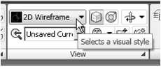
1. Select the 2D Wireframe in the Visual Styles toolbar.
• The 2D Wireframe command resets the display to the
default AutoCAD display mode. Note that this step is
required for the Invisble Edge option to work correctly.
activate the command as shown.

“_3dface Specify first point or [invisible]:” is
displayed. Pick the top right corner of the
model as shown.

4. In the command prompt area, the message
“Specify second point or [invisible]:” is
displayed. Pick the top front corner of the
model as shown.

5. In the command prompt area, the message
“Specify third point or [invisible]
of the model adjacent to the previously
selected corner as shown.
---------------------------------------ber SAMBUNG -----------------------------------
20 April 2012
3D Surface Modeling --- "The ViewCube"
The ViewCube is a 3D navigation tool that appears when the 3D graphics system is
enabled. With the ViewCube, you can switch between standard and isometric views.

Once the ViewCube is displayed, it is shown in one of the corners of the graphics
window over the model in an inactive state. The ViewCube also provides visual
feedback about the current viewpoint of the model as view changes occur. When the
cursor is positioned over the ViewCube, it becomes active and allows you to switch to
one of the available preset views, roll the current view, or change to the Home view of
the model.

1. Move the cursor over the ViewCube and noticed the
different sides of the ViewCube become highlighted and
can be activated.
2. Single left-mouse-click when the Front side is activated as
shown. The current view is set to viewing the Front side.

3. Move the cursor over the Counter Clockwise arrow of
the ViewCube and notice the Orbit option becomes
highlighted.
4. Single left-mouse-click to activate the Counter
Clockwise option as shown. The current view is orbited
90 degrees; we are still viewing the Front side.

5. Move the cursor over the Left arrow of the ViewCube
and notice the Orbit option becomes highlighted.
6. Single left-mouse-click to activate the Left arrow option
as shown. The current view is now set to viewing the
Top side.

7. Move the cursor over the top edge of the ViewCube
and notice the roll option becomes highlighted.
8. Single left-mouse-click to activate the Roll option as
shown. The view will be adjusted to roll 45 degrees.

9. Move the cursor over the ViewCube and drag with the
left-mouse-button to activate the Free Rotation option

The orientation of the model can
also be changed to base on either
the UCS or the WCS by clicking
on the coordinate setting option
below the ViewCube as shown.

10. Move the cursor over the Home icon of the ViewCube
and notice the Home View option becomes highlighted.
11. Single left-mouse-click to activate the Home View
option as shown. The view will be adjusted back to the
default SW Isometric view.

12. In the Visual Styles toolbar, click on the 3D Hidden icon to
display the model with hidden lines removed.
13. On your own, use the
ViewCube to rotate the
model and examine the
constructed surface model.

• Reset the display to SE Isometric view before proceed to
the next section.
3D Surface Modeling -----sambungan-------

6. Place the first corner point of the 2D solid at
the origin of the new UCS.

7. In the command prompt area, the
message “Specify second point:” is
displayed. Pick the bottom right corner
of the inclined plane as shown.

8. In the command prompt area, the
message “Specify third point:” is
displayed. Pick the corner directly
above the origin of the UCS as
shown.
• The 2D Solid command requires the third point to be specified diagonally opposite to
the second point. This seemly strange way of specifying the third corner was
established when the 2D Solid command was first introduced back in the mid-1980s.
Note that the 3D Face command, the second-generation surface command in
AutoCAD, does not follow this convention.

9. In the command prompt area, the
message “Specify fourth point or
[Exit]:” is displayed. Pick the
corner directly above the second
point we selected as shown in the
figure.
10. Inside the graphics window, rightmouse-
click once to end the 2D
Solid command.
• The 2D Solid command allows the creation of three-sided or four-sided filled
polygons, which can be used to represent faces of surface models. Note that in the
above steps, we could accept the three-sided polygon after defining the third corner.
18 April 2012
AutoCAD® 2010 Tutorial-Randy H. Shih Oregon Institute of Technology


4. Inside the arcball, press down the
left-mouse-button and drag it to
rotate the model freely in 3D space.
Observe the display of the shaded
surface in contrast to the 3D
wireframe edges that are located
behind it.

5. In the UCS toolbar, select the World UCS. This
option resets the UCS to align to the world
coordinate system.

6. On your own, reset the display to the SE Isometric
View before continuing to the next section.
Creating a Surface Using the 3D Face Command
• The second generation of surface command made available in AutoCAD was the 3D
Face command. The 3D Face command can be used to create true 3D planar
surfaces by allowing the X, Y and Z coordinates of the corners to be selected
independently of the current UCS. The created polygon can be a three-sided or foursided
shape. This command is the primary construction tool for surface modeling in
AutoCAD.

1. In the Menu Bar, select [Draw] [Modeling] [Meshes] [3D Face].


2. In the command prompt area, the
message “_3dface Specify first point or
[invisible]:” is displayed. Pick the lower
right corner of the vertical inclined face
of the model as shown.

3. In the command prompt area, the message
“Specify second point or [invisible]:” is
displayed. Pick the adjacent corner above
the previous selected corner of the vertical
inclined face as shown.

4. In the command prompt area, the
message “Specify third point or
[invisible]:” is displayed. Pick the
adjacent corner of the right vertical
face of the model as shown.

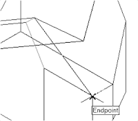
5. In the command prompt area, the message
“Specify fourth point or [invisible] <Create
three-sided face>:” is displayed. Pick the
corner below the last selected corner as shown.
-----------------------------------bersambung--------------------------------------------
Salam Cerca trova - man Jadda wa Jada
17 April 2012
AutoCAD® 2010 Tutorial-Second Level: 3D Modeling
Using the Visual Styles Toolbar
1. Move the cursor to the View toolbar panel
and left-click on the downward triangle to
display a list of available options.
Five Visual Styles are available.

 2. Click on the Realistic Visual Style icon to display the
shaded image of the model.

There exists only one surface in our model.
The surface was created with the 2D Solid
command.
1. Move the cursor to the View toolbar panel
and left-click on the downward triangle to
display a list of available options.
Five Visual Styles are available.

• 2D Wireframe: Displays the objects using lines and
curves to represent the boundaries of objects created.
Linetypes and lineweights are visible with this option.
Note that this is the default AutoCAD display mode.
• 3D Hidden: Displays the objects using the 3D
wireframe representation with lines that are located
behind surfaces and solids removed.
• 3D Wireframe: Displays the objects using lines and
curves to represent the boundaries of objects created.
Displays a shaded 3D user coordinate system (UCS)
icon. Note that linetypes and lineweights are not
visible with this option.
• Conceptual Visual Style: Creates a shaded image
of polygon faces and solids that uses the Gooch face
style, a transition between cool and warm colors rather
than dark to light. The effect is less realistic, but it can
make the details of the model easier to see.
• Realistic Visual Style: Creates a shaded image of
polygon faces and solids that gives the objects a
smooth and realistic appearance.

shaded image of the model.

The surface was created with the 2D Solid
command.
AutoCAD® 2010 Tutorial---continue

3. In the command prompt area, the message
“Specify point on positive portion of X-axis:”
is displayed. Pick the adjacent corner toward
the right side of the model as shown.

message “Specify point on positive
portion of X-axis:” is displayed. Pick
the right corner of the inclined plane
as shown.
• The new UCS is aligned to the
vertical inclined plane as shown.

Solid to activate the 2D Solid
command as shown


the origin of the new UCS.

7. In the command prompt area, the
message “Specify second point:” is
displayed. Pick the bottom right corner
of the inclined plane as shown.

8. In the command prompt area, the
message “Specify third point:” is
displayed. Pick the corner directly
above the origin of the UCS as
shown.
• The 2D Solid command requires the third point to be specified diagonally opposite to
the second point. This seemly strange way of specifying the third corner was
established when the 2D Solid command was first introduced back in the mid-1980s.
Note that the 3D Face command, the second-generation surface command in
AutoCAD, does not follow this convention.

9. In the command prompt area, the
message “Specify fourth point or
[Exit]:” is displayed. Pick the
corner directly above the second
point we selected as shown in the
figure.
10. Inside the graphics window, rightmouse-
click once to end the 2D
Solid command.
• The 2D Solid command allows the creation of three-sided or four-sided filled
polygons, which can be used to represent faces of surface models. Note that in the
above steps, we could accept the three-sided polygon after defining the third corner.
---------------------------------to be continued---------------------------------------------------
Langganan:
Postingan (Atom)