.....sambungan

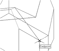
6. In the command prompt area, the message “Specify
fourth point or [invisible]
face>:” is displayed. Pick the corner below the last
selected corner as shown.
8. In the Visual Styles toolbar, click on the 3D Hidden icon
to display the model with hidden lines removed. Note that
the edges of the polygons are displayed as shown.
9. On your own, examine
the model by selecting
the different Visual
Styles.
10. Rest the Visual Styles toolbar to 2D
Wireframe, the default AutoCAD display
mode.
Using the Invisible Edge Option
• The Invisible Edge option is used to turn off the display of selected edges and
therefore allow the adjacent polygons, created by the 3D Face command, to
appear as being joined together.

6. In the command prompt area, the message “Specify
fourth point or [invisible]
face>:” is displayed. Pick the corner below the last
selected corner as shown.
7. On your own, repeat the zigzagging
pattern to define polygons until all
corners of the inclined surface have been
selected and additional polygons are
created as shown in the figure. Note that
the last polygon we created is a threesided
polygon.
8. In the Visual Styles toolbar, click on the 3D Hidden icon
to display the model with hidden lines removed. Note that
the edges of the polygons are displayed as shown.
9. On your own, examine
the model by selecting
the different Visual
Styles.
10. Rest the Visual Styles toolbar to 2D
Wireframe, the default AutoCAD display
mode.
Using the Invisible Edge Option
• The Invisible Edge option is used to turn off the display of selected edges and
therefore allow the adjacent polygons, created by the 3D Face command, to
appear as being joined together.


Tidak ada komentar:
Posting Komentar