Tampilkan postingan dengan label Mekanikal. Tampilkan semua postingan

13 Mei 2012

AutoCAD® 2010 Tutorial - "Creating a Surface of Irregular Shape"

.....sambungan


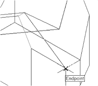
6. In the command prompt area, the message “Specify
fourth point or [invisible]
face>:” is displayed. Pick the corner below the last
selected corner as shown.


7. On your own, repeat the zigzagging
pattern to define polygons until all
corners of the inclined surface have been
selected and additional polygons are
created as shown in the figure. Note that
the last polygon we created is a threesided
polygon.


8. In the Visual Styles toolbar, click on the 3D Hidden icon
to display the model with hidden lines removed. Note that
the edges of the polygons are displayed as shown.


9. On your own, examine
the model by selecting
the different Visual
Styles.


10. Rest the Visual Styles toolbar to 2D
Wireframe, the default AutoCAD display
mode.


Using the Invisible Edge Option


• The Invisible Edge option is used to turn off the display of selected edges and
therefore allow the adjacent polygons, created by the 3D Face command, to
appear as being joined together.


18 April 2012

AutoCAD® 2010 Tutorial-Randy H. Shih Oregon Institute of Technology

3. Select Free Orbit in the View toolbar as shown.


4. Inside the arcball, press down the
left-mouse-button and drag it to
rotate the model freely in 3D space.
Observe the display of the shaded
surface in contrast to the 3D
wireframe edges that are located
behind it.


5. In the UCS toolbar, select the World UCS. This
option resets the UCS to align to the world
coordinate system.


6. On your own, reset the display to the SE Isometric
View before continuing to the next section.


Creating a Surface Using the 3D Face Command

• The second generation of surface command made available in AutoCAD was the 3D
Face command. The 3D Face command can be used to create true 3D planar
surfaces by allowing the X, Y and Z coordinates of the corners to be selected
independently of the current UCS. The created polygon can be a three-sided or foursided
shape. This command is the primary construction tool for surface modeling in
AutoCAD.


1. In the Menu Bar, select [Draw] [Modeling] [Meshes] [3D Face].


2. In the command prompt area, the
message “_3dface Specify first point or
[invisible]:” is displayed. Pick the lower
right corner of the vertical inclined face
of the model as shown.


3. In the command prompt area, the message
“Specify second point or [invisible]:” is
displayed. Pick the adjacent corner above
the previous selected corner of the vertical
inclined face as shown.


4. In the command prompt area, the
message “Specify third point or
[invisible]:” is displayed. Pick the
adjacent corner of the right vertical
face of the model as shown.


5. In the command prompt area, the message
“Specify fourth point or [invisible] <Create
three-sided face>:” is displayed. Pick the
corner below the last selected corner as shown.


-----------------------------------bersambung--------------------------------------------

Salam Cerca trova - man Jadda wa Jada


17 April 2012

AutoCAD® 2010 Tutorial---continue


3. In the command prompt area, the message
“Specify point on positive portion of X-axis:”
is displayed. Pick the adjacent corner toward
the right side of the model as shown.


4. In the command prompt area, the
message “Specify point on positive
portion of X-axis:” is displayed. Pick
the right corner of the inclined plane
as shown.
• The new UCS is aligned to the
vertical inclined plane as shown.


5. In the command prompt area, enter
Solid to activate the 2D Solid
command as shown


   6. Place the first corner point of the 2D solid at
the origin of the new UCS.


7. In the command prompt area, the
message “Specify second point:” is
displayed. Pick the bottom right corner
of the inclined plane as shown.


8. In the command prompt area, the
message “Specify third point:” is
displayed. Pick the corner directly
above the origin of the UCS as
shown.

• The 2D Solid command requires the third point to be specified diagonally opposite to
the second point. This seemly strange way of specifying the third corner was
established when the 2D Solid command was first introduced back in the mid-1980s.
Note that the 3D Face command, the second-generation surface command in
AutoCAD, does not follow this convention.


9. In the command prompt area, the
message “Specify fourth point or
[Exit]:” is displayed. Pick the
corner directly above the second
point we selected as shown in the
figure.
10. Inside the graphics window, rightmouse-
click once to end the 2D
Solid command.

• The 2D Solid command allows the creation of three-sided or four-sided filled
polygons, which can be used to represent faces of surface models. Note that in the
above steps, we could accept the three-sided polygon after defining the third corner.

---------------------------------to be continued---------------------------------------------------


AutoCAD® 2010 Tutorial-Randy H. Shih Oregon Institute of Technology


Second Level: 3D Modeling


3D Surface Modeling

Learning Objectives :
* Create 3D surfaces models
* Understand and Apply the different surface modelling Techniques
* Understand the use of 2D SOLID Command
* Understand of use of 3D FACE Command
* Use the hidden EDGE Option

Introduction
As illustrated in the previous chapters, there are no surfaces in a wireframe model; it
consists only of points, lines, and curves that describe the edges of the object. Surface
modeling was developed to provide the surface information that is missing in wireframe
modeling. Essentially, defining the skin of a design creates a surface model. Although it
is possible to create a surface model without using a wireframe model, in most cases it is
much easier to create a surface model on top of a wireframe model. In surface modeling,
a wireframe model can be used to provide information about the edges and corners so
that the desired faces can be easily positioned and placed.

Surface modeling is more sophisticated than wireframe modeling in that surface modelers
define not only the edges of 3D objects, but also the surfaces. Surface modeling provides
hiding, shading, and rendering capabilities that are not available in wireframe modeling.
Surface models do not provide the physical properties that solid models provide, such as
mass, weight, center of gravity, and so on.


The AutoCAD surface modeler defines faceted surfaces using a filled polygon. The
created faces of surface models are only planar, which means the surface models can only
have approximate curved surfaces. It is important to note that the AutoCAD surface
modeler does not create true curved surfaces. To differentiate these two types of surfaces,
faceted surfaces are called meshes in AutoCAD. Because of the use of faceted
approximation on true curved surfaces, the computer requirements of most faceted
surface modelers are typically much less than that of solid modelers. Faceted surface
modeling usually provides reasonably good representations of 3D designs with fast
rendering and shading capabilities. Faceted surface models are also useful for creating
geometry with unusual surface patterns, such as a 3D topographical model of
mountainous terrain.


AutoCAD®2010 provides three basic methods for creating surfaces – the 2D Solid, 3D
Face and Region commands. The three commands were
developed parallel to the
historical development of the different types of computer modelers.

2D Solid: The first generation surface command available in AutoCAD. Used
mostly to fill an area in the sketch plane of the current UCS. This type of surface is
not a true 3D surface.
3D Face: Creates a true 3D planar surface (allowing X, Y and Z coordinates) of
three-sided or four-sided shape. This is the type of surface developed primarily for
creating faceted surface models.
Region: Creates a 2D surface of arbitrary shape from existing 2D entities. This
command creates the most flexible and the most complicated type of surface
available in AutoCAD. This command was developed to allow manipulation of 2D
surfaces using one of the solid modeling construction techniques, namely, the
Constructive Solid Geometry method.


Although all three commands

15 April 2012

komponen AC outdoor

Komponen listrik yg berada pada outdoor unit adalah:


1. running capasitor
2. fan capasitor
3. fan motor
4. overload compressor
5. komponen pcb (untuk ac split type multi)

1. Running capasitor berfungsi menyimpan muatan listrik untuk menbantu gerak motor pertama atau start compressor.

Kerusakan running capasitor dapat diketahui dengan menggunakan multitester yaitu dengan cara:
posisikan knop multitester pada skala ohm/tahanan X 1000 lalu tempelkan kedua probe multitester kepada dua kaki terminal running capasitor kemudian lihat pada waktu anda menempelkan kabel probe – dan +, apa jarum penunjuk pada multitester bergerak kekanan lalu kembali lagi kekiri dengan cepat?
bila “ya” berarti running capasitor dalam kondisi baik, bila jarum multitester tidak kembali lagi kekiri dengan cepat berarti running capasitor rusak.


2. Fan capasitor berfungsi untuk membantu start pertama pada fan motor outdoor unit, cara mengetahui kerusakan fan capasitor sama dengan cara mengetahui kerusakan pada running capasitor.

14 April 2012

Mengenal bagian Air Conditioner


Kompresor 
Merupakan bagian yang paling penting dari mesin pendingin, kompresor menekan bahan pendingin kesemua bagian dri system. Pada system refrigerasi kompresor bekerja membuat perbedaan tekanan pada masing – masing bagian. Karena dengan adanya perbedaan antara sisi tekanan tinggi dan tekanan rendah, maka bahan pendingin cair dapat melalui alat pengatur aliran ke evaporator.
Fungsi kompresor sendiri adalah menghisap gas refrigerant dari evaporator yang bertekanan dan bertemperatur rendah kemudian memampatkan gas tersebut menjadi gas yang bertekanan dan bertemperatur yang tinggi.

Kondensor
Adalah alat untuk membuat kondensasibahan pendingin gas dari kompresor dengan suhu tinggi dan tekanan tinggi. Untuk penempatanya sendiri, kondensor ditempatkan diluar ruangan yang sedang didinginkan, agar dapat membuang panasnya keluar.
Kondensor merupakan jaringan pipa yang berfungsi sebagai pengembunan. Refrigerant yang yang dipompakan dari kompresor akan mengalami penekanan sehingga mengalir ke pipa kondensor, kemudian mengalami pengembunan. Dari sini refrigerant yang sudah mengembun dan menjadi zat cair akan mengalir menuju pipa evaporator.

Evaporator
Evaporator merupakan jaringan pipa yang berfungsi sebagai penguapan. Zat cair yang berasal dari pipa kondensor masuk ke evaporator lalu berubah wujud menjadi gas dingin karena mengalami penguapan. Selanjutnya udara tersebut mampu menyerap kondisi yang ada dalam ruangan mesin pendingin. Selanjutnya