Tampilkan postingan dengan label otodidak. Tampilkan semua postingan

23 April 2012

AutoCAD® 2010 Tutorial - "Creating a Surface of Irregular Shape"

Creating a Surface of Irregular Shape


• The 3D Face command allows us to create three-sided or four-sided polygons. For
surfaces of irregular shape, the Invisible Edge option is available in conjunction with
the 3D Face command. Note that the Invisible Edge option cannot be applied to
polygons created by the 2D Solid command.

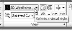
1. Select the 2D Wireframe in the Visual Styles toolbar.

• The 2D Wireframe command resets the display to the
default AutoCAD display mode. Note that this step is
required for the Invisble Edge option to work correctly.


2. In the command prompt area, enter 3dface to
activate the command as shown.


   3. In the command prompt area, the message
“_3dface Specify first point or [invisible]:” is
displayed. Pick the top right corner of the
model as shown.


4. In the command prompt area, the message
“Specify second point or [invisible]:” is
displayed. Pick the top front corner of the
model as shown.


5. In the command prompt area, the message
“Specify third point or [invisible]
:” is displayed. Pick the top corner
of the model adjacent to the previously
selected corner as shown.


---------------------------------------ber SAMBUNG  -----------------------------------


20 April 2012

3D Surface Modeling --- "The ViewCube"


The ViewCube is a 3D navigation tool that appears when the 3D graphics system is
enabled. With the ViewCube, you can switch between standard and isometric views.


Once the ViewCube is displayed, it is shown in one of the corners of the graphics
window over the model in an inactive state. The ViewCube also provides visual
feedback about the current viewpoint of the model as view changes occur. When the
cursor is positioned over the ViewCube, it becomes active and allows you to switch to
one of the available preset views, roll the current view, or change to the Home view of
the model.


1. Move the cursor over the ViewCube and noticed the
different sides of the ViewCube become highlighted and
can be activated.
2. Single left-mouse-click when the Front side is activated as
shown. The current view is set to viewing the Front side.


3. Move the cursor over the Counter Clockwise arrow of
the ViewCube and notice the Orbit option becomes
highlighted.

4. Single left-mouse-click to activate the Counter
Clockwise option as shown. The current view is orbited
90 degrees; we are still viewing the Front side.


5. Move the cursor over the Left arrow of the ViewCube
and notice the Orbit option becomes highlighted.

6. Single left-mouse-click to activate the Left arrow option
as shown. The current view is now set to viewing the
Top side.


7. Move the cursor over the top edge of the ViewCube
and notice the roll option becomes highlighted.

8. Single left-mouse-click to activate the Roll option as
shown. The view will be adjusted to roll 45 degrees.


9. Move the cursor over the ViewCube and drag with the
left-mouse-button to activate the Free Rotation option


The orientation of the model can
also be changed to base on either
the UCS or the WCS by clicking
on the coordinate setting option
below the ViewCube as shown.


10. Move the cursor over the Home icon of the ViewCube
and notice the Home View option becomes highlighted.

11. Single left-mouse-click to activate the Home View
option as shown. The view will be adjusted back to the
default SW Isometric view.


12. In the Visual Styles toolbar, click on the 3D Hidden icon to
display the model with hidden lines removed.


13. On your own, use the
ViewCube to rotate the
model and examine the
constructed surface model.


• Reset the display to SE Isometric view before proceed to
the next section.


3D Surface Modeling -----sambungan-------


6. Place the first corner point of the 2D solid at
the origin of the new UCS.


7. In the command prompt area, the
message “Specify second point:” is
displayed. Pick the bottom right corner
of the inclined plane as shown.


8. In the command prompt area, the
message “Specify third point:” is
displayed. Pick the corner directly
above the origin of the UCS as
shown.


• The 2D Solid command requires the third point to be specified diagonally opposite to
the second point. This seemly strange way of specifying the third corner was
established when the 2D Solid command was first introduced back in the mid-1980s.
Note that the 3D Face command, the second-generation surface command in
AutoCAD, does not follow this convention.


9. In the command prompt area, the
message “Specify fourth point or
[Exit]:” is displayed. Pick the
corner directly above the second
point we selected as shown in the
figure.


10. Inside the graphics window, rightmouse-
click once to end the 2D
Solid command.


• The 2D Solid command allows the creation of three-sided or four-sided filled
polygons, which can be used to represent faces of surface models. Note that in the
above steps, we could accept the three-sided polygon after defining the third corner.


18 April 2012

AutoCAD® 2010 Tutorial-Randy H. Shih Oregon Institute of Technology

3. Select Free Orbit in the View toolbar as shown.


4. Inside the arcball, press down the
left-mouse-button and drag it to
rotate the model freely in 3D space.
Observe the display of the shaded
surface in contrast to the 3D
wireframe edges that are located
behind it.


5. In the UCS toolbar, select the World UCS. This
option resets the UCS to align to the world
coordinate system.


6. On your own, reset the display to the SE Isometric
View before continuing to the next section.


Creating a Surface Using the 3D Face Command

• The second generation of surface command made available in AutoCAD was the 3D
Face command. The 3D Face command can be used to create true 3D planar
surfaces by allowing the X, Y and Z coordinates of the corners to be selected
independently of the current UCS. The created polygon can be a three-sided or foursided
shape. This command is the primary construction tool for surface modeling in
AutoCAD.


1. In the Menu Bar, select [Draw] [Modeling] [Meshes] [3D Face].


2. In the command prompt area, the
message “_3dface Specify first point or
[invisible]:” is displayed. Pick the lower
right corner of the vertical inclined face
of the model as shown.


3. In the command prompt area, the message
“Specify second point or [invisible]:” is
displayed. Pick the adjacent corner above
the previous selected corner of the vertical
inclined face as shown.


4. In the command prompt area, the
message “Specify third point or
[invisible]:” is displayed. Pick the
adjacent corner of the right vertical
face of the model as shown.


5. In the command prompt area, the message
“Specify fourth point or [invisible] <Create
three-sided face>:” is displayed. Pick the
corner below the last selected corner as shown.


-----------------------------------bersambung--------------------------------------------

Salam Cerca trova - man Jadda wa Jada


17 April 2012

AutoCAD® 2010 Tutorial-Second Level: 3D Modeling

Using the Visual Styles Toolbar


1. Move the cursor to the View toolbar panel
and left-click on the downward triangle to
display a list of available options.
Five Visual Styles are available.


• 2D Wireframe: Displays the objects using lines and
curves to represent the boundaries of objects created.
Linetypes and lineweights are visible with this option.
Note that this is the default AutoCAD display mode.
• 3D Hidden: Displays the objects using the 3D
wireframe representation with lines that are located
behind surfaces and solids removed.
• 3D Wireframe: Displays the objects using lines and
curves to represent the boundaries of objects created.
Displays a shaded 3D user coordinate system (UCS)
icon. Note that linetypes and lineweights are not
visible with this option.

• Conceptual Visual Style: Creates a shaded image
of polygon faces and solids that uses the Gooch face
style, a transition between cool and warm colors rather
than dark to light. The effect is less realistic, but it can
make the details of the model easier to see.
• Realistic Visual Style: Creates a shaded image of
polygon faces and solids that gives the objects a
smooth and realistic appearance.


2. Click on the Realistic Visual Style icon to display the
shaded image of the model.


There exists only one surface in our model.
The surface was created with the 2D Solid
command.


AutoCAD® 2010 Tutorial---continue


3. In the command prompt area, the message
“Specify point on positive portion of X-axis:”
is displayed. Pick the adjacent corner toward
the right side of the model as shown.


4. In the command prompt area, the
message “Specify point on positive
portion of X-axis:” is displayed. Pick
the right corner of the inclined plane
as shown.
• The new UCS is aligned to the
vertical inclined plane as shown.


5. In the command prompt area, enter
Solid to activate the 2D Solid
command as shown


   6. Place the first corner point of the 2D solid at
the origin of the new UCS.


7. In the command prompt area, the
message “Specify second point:” is
displayed. Pick the bottom right corner
of the inclined plane as shown.


8. In the command prompt area, the
message “Specify third point:” is
displayed. Pick the corner directly
above the origin of the UCS as
shown.

• The 2D Solid command requires the third point to be specified diagonally opposite to
the second point. This seemly strange way of specifying the third corner was
established when the 2D Solid command was first introduced back in the mid-1980s.
Note that the 3D Face command, the second-generation surface command in
AutoCAD, does not follow this convention.


9. In the command prompt area, the
message “Specify fourth point or
[Exit]:” is displayed. Pick the
corner directly above the second
point we selected as shown in the
figure.
10. Inside the graphics window, rightmouse-
click once to end the 2D
Solid command.

• The 2D Solid command allows the creation of three-sided or four-sided filled
polygons, which can be used to represent faces of surface models. Note that in the
above steps, we could accept the three-sided polygon after defining the third corner.

---------------------------------to be continued---------------------------------------------------


AutoCAD® 2010 Tutorial-Randy H. Shih Oregon Institute of Technology


Second Level: 3D Modeling


3D Surface Modeling

Learning Objectives :
* Create 3D surfaces models
* Understand and Apply the different surface modelling Techniques
* Understand the use of 2D SOLID Command
* Understand of use of 3D FACE Command
* Use the hidden EDGE Option

Introduction
As illustrated in the previous chapters, there are no surfaces in a wireframe model; it
consists only of points, lines, and curves that describe the edges of the object. Surface
modeling was developed to provide the surface information that is missing in wireframe
modeling. Essentially, defining the skin of a design creates a surface model. Although it
is possible to create a surface model without using a wireframe model, in most cases it is
much easier to create a surface model on top of a wireframe model. In surface modeling,
a wireframe model can be used to provide information about the edges and corners so
that the desired faces can be easily positioned and placed.

Surface modeling is more sophisticated than wireframe modeling in that surface modelers
define not only the edges of 3D objects, but also the surfaces. Surface modeling provides
hiding, shading, and rendering capabilities that are not available in wireframe modeling.
Surface models do not provide the physical properties that solid models provide, such as
mass, weight, center of gravity, and so on.


The AutoCAD surface modeler defines faceted surfaces using a filled polygon. The
created faces of surface models are only planar, which means the surface models can only
have approximate curved surfaces. It is important to note that the AutoCAD surface
modeler does not create true curved surfaces. To differentiate these two types of surfaces,
faceted surfaces are called meshes in AutoCAD. Because of the use of faceted
approximation on true curved surfaces, the computer requirements of most faceted
surface modelers are typically much less than that of solid modelers. Faceted surface
modeling usually provides reasonably good representations of 3D designs with fast
rendering and shading capabilities. Faceted surface models are also useful for creating
geometry with unusual surface patterns, such as a 3D topographical model of
mountainous terrain.


AutoCAD®2010 provides three basic methods for creating surfaces – the 2D Solid, 3D
Face and Region commands. The three commands were
developed parallel to the
historical development of the different types of computer modelers.

2D Solid: The first generation surface command available in AutoCAD. Used
mostly to fill an area in the sketch plane of the current UCS. This type of surface is
not a true 3D surface.
3D Face: Creates a true 3D planar surface (allowing X, Y and Z coordinates) of
three-sided or four-sided shape. This is the type of surface developed primarily for
creating faceted surface models.
Region: Creates a 2D surface of arbitrary shape from existing 2D entities. This
command creates the most flexible and the most complicated type of surface
available in AutoCAD. This command was developed to allow manipulation of 2D
surfaces using one of the solid modeling construction techniques, namely, the
Constructive Solid Geometry method.


Although all three commands

15 April 2012

komponen AC outdoor

Komponen listrik yg berada pada outdoor unit adalah:


1. running capasitor
2. fan capasitor
3. fan motor
4. overload compressor
5. komponen pcb (untuk ac split type multi)

1. Running capasitor berfungsi menyimpan muatan listrik untuk menbantu gerak motor pertama atau start compressor.

Kerusakan running capasitor dapat diketahui dengan menggunakan multitester yaitu dengan cara:
posisikan knop multitester pada skala ohm/tahanan X 1000 lalu tempelkan kedua probe multitester kepada dua kaki terminal running capasitor kemudian lihat pada waktu anda menempelkan kabel probe – dan +, apa jarum penunjuk pada multitester bergerak kekanan lalu kembali lagi kekiri dengan cepat?
bila “ya” berarti running capasitor dalam kondisi baik, bila jarum multitester tidak kembali lagi kekiri dengan cepat berarti running capasitor rusak.


2. Fan capasitor berfungsi untuk membantu start pertama pada fan motor outdoor unit, cara mengetahui kerusakan fan capasitor sama dengan cara mengetahui kerusakan pada running capasitor.

Belajar mengisi freon ac split


Belajar mengisi freon ac split

Pertama-tama yg harus dilakukan dalam pengisian freon adalah mengoperasikan ac split.
setelah outdoor unit mendapatkan supply listrik dari indoor unit, buka nepel penutup pentil pengisian freon dengan kunci inggris.
lalu pasang selang berwarna biru yg berada pada manifold di pentil pengisian freon, adakah tekanan freon? dengan melihat jarum manifold tekanan rendah yg berwarna biru.
jika tidak ada tekanan freon sama sekali, berarti sistem pendingin/ac split ada kebocoran.
cari sampai ketemu dimana letak kebocorannya dengan kuas kecil yg diberi air sabun, bila tidak diperbaiki/dilas kebocorannya freon akan berkurang kembali walaupun telah diisi sampai ac split menjadi dingin kembali.
bila ruang kebocorannya harus diperbaiki dengan cara mengelas dan pada sistem pendingin/ac split masih terdapat sisa freon, maka yg harus anda lakukan sebelum melakukan perbaikan/pengelasan adalah membuang sisa freon tersebut agar tidak membahayakan diri anda.

apabila telah ditemukan letak kebocorannya dan sudah diperbaiki/dilas, sistim pendingin/ac split harus divakum terlebih dahulu sebelum diisi freon, dengan menggunakan

Tutorial AutoCAD untuk Pemula

‘teknik belajar AutoCAD sendiri’ alias belajar otodidak  merupakan cara yg paling ampuh dan cerdik untuk menjadi mahir di bidang tertentu, nah kali ini mengurai mengenai konsep cara penggunaan AutoCAD, sehingga anda dapat mencoba sendiri menggunakan tool-tool yang ada.


Interface dan Penggunaan Tool

14 April 2012

Menguji Dioda


Dengan jangkah OHM x1 k atau x100 penyidik merah ditempel pada katoda (ada tanda gelang) dan hitam pada anoda, jarum harus ke kanan.

Penyidik dibalik ialah merah ke anoda dan hitam ke katoda, jarum harus tidak bergerak. Bila tidak demikian berarti kemungkinan diode rusak.

Cara demikian juga dapat digunakan untuk mengetahui mana anoda dan mana katoda dari suatu diode yang gelangnya terhapus.


Dengan jangkah VDC, bahan suatu dioda dapat juga diperkirakan dengan circuit pada gambar berikut ini.
Bila tegangan katoda¬ anoda 0.2 V, maka kemungkinan dioda germanium, dan bila 0.6V kemungkinan dioda silicon.


Salaaam Cerca trova-man Jadda wa jada

Menguji-mengukur Kondensator

Sebelumnya, muatan kondensator didischarge. Dengan jangkah pada OHM, tempelkan penyidik merah pada kutub POS dan hitam pada MIN.


Bila jarum menyimpang ke KANAN dan kemudian secara berangsur-¬angsur kembali ke KIRI, berarti kondensator baik.

Bila jarum tidak bergerak, kondensator putus dan bila jarum mentok ke kanan dan tidak balik, kemungkinan kondensator bocor.
Untuk menguji elco 10 F jangkah pada x10 k atau 1 k. Untuk kapasitas sampai 100 F jangkah pada x100, di atas 1000 F, jangkah x1 dan menguji kondensator non elektrolit jangkah pada x10 k.

Menguji Hubungan Pada Circuit / Rangkaian
Suatu circuit atau bisa juga kumparan trafo diperiksa resistansinya, dan koneksi baik bila resistansinya menunjukkan angka NOL.

Salam Cerca trova - man Jadda wa jada

Mengenal bagian Air Conditioner


Kompresor 
Merupakan bagian yang paling penting dari mesin pendingin, kompresor menekan bahan pendingin kesemua bagian dri system. Pada system refrigerasi kompresor bekerja membuat perbedaan tekanan pada masing – masing bagian. Karena dengan adanya perbedaan antara sisi tekanan tinggi dan tekanan rendah, maka bahan pendingin cair dapat melalui alat pengatur aliran ke evaporator.
Fungsi kompresor sendiri adalah menghisap gas refrigerant dari evaporator yang bertekanan dan bertemperatur rendah kemudian memampatkan gas tersebut menjadi gas yang bertekanan dan bertemperatur yang tinggi.

Kondensor
Adalah alat untuk membuat kondensasibahan pendingin gas dari kompresor dengan suhu tinggi dan tekanan tinggi. Untuk penempatanya sendiri, kondensor ditempatkan diluar ruangan yang sedang didinginkan, agar dapat membuang panasnya keluar.
Kondensor merupakan jaringan pipa yang berfungsi sebagai pengembunan. Refrigerant yang yang dipompakan dari kompresor akan mengalami penekanan sehingga mengalir ke pipa kondensor, kemudian mengalami pengembunan. Dari sini refrigerant yang sudah mengembun dan menjadi zat cair akan mengalir menuju pipa evaporator.

Evaporator
Evaporator merupakan jaringan pipa yang berfungsi sebagai penguapan. Zat cair yang berasal dari pipa kondensor masuk ke evaporator lalu berubah wujud menjadi gas dingin karena mengalami penguapan. Selanjutnya udara tersebut mampu menyerap kondisi yang ada dalam ruangan mesin pendingin. Selanjutnya

11 April 2012

Bisnis Besar dan Menguntungkan, Dimanakah Engkau Berada?


.
Ok, tema kali adalah tentang bisnis apa yang bisa berkembang menjadi besar dan terus menghasilkan keuntungan. Pertanyaan tentang “bisnis apa yang bisa besar dan menguntungkan” selalu saja menjadi“hot question” bagi orang yang ingin memulai bisnis.
Awal mencari-cari ide bisnis apa yang bisa besar dan menguntungkan. Mulai dari buka usaha di halaman rumah hingga merancang usaha cuci motor. Waktu itu semuanya nampak seperti bisnis yang kecil.
Menurut Robert T. Kiyosaki, masalah bisnis besar atau tidak itu tergantung dari spektrum anda.
Anda tahu spektrum? Spektrum adalah cara pandang anda terhadap sebuah bisnis atau usaha. Anggap saja anda sedang menggeluti usaha bandeng presto. Bagaimana cara pandang anda terhadap usaha tersebut?
Apakah anda ingin usaha bandeng presto yang biasa-biasa saja atau usaha bandeng presto yang menggurita? Anda paham kan maksud saya? Saya beri contoh. Anda tahu burger McDonalds? Awalnya, McDonalds hanya punya satu gerai.
Sekarang anda bisa lihat, ada puluhan bahkan mungkin ratusan gerai McDonalds tersebar di dunia. Bandingkan dengan usaha burger lokal di tempat anda. Bisakah usaha tersebut menyaingi McDonalds? Kemungkinan besar tidak kan?
Saya tidak menyuruh anda untuk mempunyai mimpi setinggi langit dengan membuka usaha seperti yang Ray Kroc, si pendiri McDonalds lakukan.

4 Jenis Pasar yang Bisa Anda Bidik Untuk Usaha Anda


Kita rehat sejenak ya, supaya tidak terlalu pusing untuk membahas hal-hal yang berbau teknis bisnis seperti segmentasi pasarcross sell dan up selldiferensiasi produk dan sebagainya.
Kali ini s yang ringan-ringan saja, yaitu macam-macam pasar. Pada intinya pasar dapat dikelompokan ke dalam 4 golongan.
Anda bisa memasuki satu atau lebih dari 4 golongan atau macam pasar tersebut, disesuaikan dengan jenis dan tujuan usaha anda. Bagaimana, sudah siap? Let’s get it down, selamat membaca, monggo dinikmati artikel ringan yang satu ini…
  1. Pasar KonsumenPasar konsumen ini adalah pembeli yang membeli barang buat dikonsumsi sendiri. Bukan untuk dijual lagi, bukan juga untuk diproses lebih lanjut. Termasuk kategori pasar konsumen adalah pembeli individu dan pembeli rumah tangga non-bisnis. Barang yang dibeli adalah barang konsumsi. Anda pasti tidak asing dengan jenis pasar model seperti ini. Pasar konsumen ini lebih mudah dimasuki daripada jenis pasar yang lain, apalagi jika anda menerapkan taktik pemasaranyang tepat.
  2. Pasar Industri
    Di pasar industri, pembelinya bisa individu, lembaga atau organisasi. Mereka membeli barang untuk dipakai sendiri, baik secara langsung maupun tidak langsung untuk digunakan memproduksi barang lain yang kemudian dijual ke konsumen. Biasanya barang yang dibeli adalah barang industri. Contohnya sabun dan vaselin untuk usaha cuci motor atau gula, buah-buahan dan es batu untuk usaha juice. Kalau anda punya barang-barang yang seperti ini, selain anda bisa jual untuk pasar konsumen, anda juga bisa jual untuk pasar industri.
  3. Pasar PenjualAdalah sebuah pasar yang terdiri atas individu atau organisasi yang membeli barang-barang dengan tujuan dijual lagi atau disewakan agar mendapatkan keuntungan atau laba. Contohnya anda buka grosir buah murah, anda jual ke pedagang eceran. Atau seperti yang saya lakukan. Beli kepiting bakau dari pengepul di Kalimantan, kemudian saya jual ke eksportir.
  4. Pasar Pemerintah
    Kalau yang satu ini, anda pasti sudah sering dengar juga. Kalau belum, saya terangkan. Pasar pemerintah ini adalah pasar dimana terdapat lembaga-lembaga pemerintah seperti departemen-departemen, direktorat, kantor-kantor dinas dan instansi lain. Contoh model bisnisnya adalah pengadaan barang. Anda bisa memasuki pasar pemerintah ini melalui tender atau lelang proyek dari pemerintah. Entah pengadaan peralatan kantor, pembangunan jalan, pengadaan seragam pegawai negeri dan sebagainya.
Sekarang dari jenis-jenis pasar diatas, mana yang akan anda bidik yang sesuai dengan tipe bisnisanda?
Salam Cerca Trova  man Jadda wa jada
(sumber gambar : berlinsianipar.wordpress.com)

Belajar Ponsel / Handphone - Basic


Kesempatan kali ini belajar dasar-dasar tentang  Perangkat Ponsel . Semoga artikel ini bisa memberikan manfaat dan pengetahuan baru tentang service ponsel.
Mari belajar bersama ...Bagian dasar pada Ponsel dikelompokkan menjadi beberapa bagian, antara lain yaitu :

1. Bagian Tegangan Adalah bagian yang memberikan tegangan pada setiap komponen terkait dan bekerja atas perintah CPU

2. Bagian Signal ( RX dan TX ) Adalah bagian yang mengatur keluar masuknya signal dan akan mengirim datanya kepada CPU untuk diolah atau diproses menjadi Gelombang suara dan display pada LCD.

3. Bagian Data (Operating System) Adalah Bagian berfungsi sebagai Operating System yang mengolah data dan yang memberi perintah kepada seluruh bagian yang terdapat pada Ponsel.

4. Bagian Audio Adalah yang mengolah proses Keluar masuknya getaran suara pada Ponsel.

bagan mesin ponsel


1.1. BAGIAN TEGANGAN

Bagian tegangan ini terbagi dari beberapa komponen yang bekerja di dalam Ponsel, komponen itu antara lain adalah :

1. Batterai
2. IC Power Supply
3. Switch On/ Off
4. CPU


1. Saat Ponsel dalam keadaan mati, Batterai tetap memberi arus/tegangan ke Ponsel. yaitu ke IC PA, IC Regulator, IC Charging, IC Interface

2. IC Power Supply mengolah dan membagi Arus/Tegangan yang masuk dari Batterai kemudian mengeluarkan Tegangan Stanby ke CPU.Apabila terjadi kerusakan pada IC Power Supply,tidak akan ada tegangan stanby/ VBB dari Power Supply. IC Power Supply akan mengeluarkan tegangan (Output) setelah Ponsel di On kan , kecuali tegangan VBB yang berfungsi sebagai tegangan stanby.

3. Saat Ponsel Di On kan,CPU mendapat tegangan Negatif (-) dari Switch On/Off, kemudian CPU memerintahkan Power Supply untuk mensupply arus/tegangan ke setiap bagian pada Ponsel

4. Dalam pengisian ulang,arus/tegangan dari Charger masuk melalui Resistor Fuse yang berfungsi sebagai Sekring, apabila terjadi arus yang berlebih masuk ke IC Charging. Arus/ Tegangan yang masuk ke IC cahrging di olah dan dikeluarkan sebagai Output harus sesuai dengan Tegangan pada Batterai. Pada Ic Charging terdapat Charging Sense sebagai pengontrol berbentuk data yang berhubungan dengan IC Power Supply, Fungsinya apabila terjadi ketidak sesuaian dengan kinerja IC Charging,maka IC Power Akan memutuskan pengisian ulang dengan mengirimkan data ke CPU bahwa pengisian gagal.Dikenal dengan istilah Not Charging / tidak mengisi.

1.2. BAGIAN SIGNAL ( RX DAN TX )

Bagian Penerimaan Signal ( RX )

Pada Bagian ini, yang bekerja bekerja pada Ponsel terdiri dari beberapa komponen, komponen ini antara lain adalah :

1. Antena
2. Switch Antena/Duplexer
3. Filter RX (Penyaring)
4. Transistor (Sebagai Penguat RX)
5. IC RF/RF Proceccor
6. VCO
7. IC Power Supply


Untuk mengetahui bekerja atau tidaknya bagian RX,dapat diketahui dengan melihat dari setting Manual Network.Jika tidak mendapatkan daftar jaringan Operator, maka dapat dipastikan bahwa bagian RX bermasalah.

System kerja Komponen bagian RX :

1. Sinyal yang ditangkap/diterima oleh Antena diteruskan ke Switch Antena sebagai terminal

2. Switch Antena akan mengeluarkan dua Sinyal R bagi Ponsel Dual Band,yaitu DCS-RX(1800Mhz) & GSM-RX (900Mhz).kedua sinyal tersebut diteruskan Ke Filter sebagai sinyal RX,Sinyal RX akan disaring dan diteruskan ke Transistor sebagai penguat. Pada transistor kedua sinyal RX diperkuat untuk dapat diteruskan ke Filter untuk kembali disaring dan membagi sinyal menjadi 4 bagian,yaitu mengeluarkan dua sinyal DCS-RX dan Dua sinyal GSM-RX yang akan diteruskan ke IC RF.

3. IC RF/IF Mengolah sinyal RX dan disesuaikan dengan Frekwensi yang dibentuk oleh VCO.

Bagian Signal Pemancaran ( TX )
Pada Bagian ini,yang bekerja bekerja pada Ponsel terdiri dari beberapa komponen, komponen ini antara lain adalah :

1. Antena
2. Switch Antena
3. Filter TX ( Penyaring )
4. IC PA
5. IC RF
6. VCO
7. IC Power Supply

Untuk mengetahui bekerja atau tidaknya bagian TX (Pemancaran), dapat digunakan lampu radiasi, multitester, dan melakukan panggilan ke nomer SOS/Emergency (ke 112) tanpa simCard terpasang.

Cara melakukannya pengecekan dengan multitester adalah :

1. Hidupkan Ponsel dengan atau tanpa menggunakan Sim Card
2. Lakukan panggilan keluar
3. Tempelkan multitester di dekat bagian antenna (kalibrasi Multitester pada AC 10V)
4. Apabila jarum multitester bergerak, berarti TX bekerja.

System kerja Komponen bagian TX

1. VCO membentuk frekwensi yang akan diproses oleh IC RF membentuk empat sinyal Output,yaitu Dua sinyal DCS-TX dan Dua GSM-TX untuk di teruskan ke bagian Filter TX (Pemancaran).VCO jg berfungsi sebagai Power Detector untuk mengatur tegangan pulsa dari IC RF dalam pengiriman data ke CPU.

2. Pada Filter keempat sinyal Output yang di kirim oleh IC RF di bentuk menjadi dua sinyal TX,yaitu DCS dan GSM untuk diteruskan ke IC PA

3. Pada IC PA kedua sinyal tersebut diperkuat untuk pemancaran kemudian diteruskan ke Filter TX.

4. Pada Filter Kedua sinyal tersebut disaring dan diteruskan ke bagian Switch Antena

5. Switch Antena yang berfungsi sebagai terminal dan menggabungkan kedua sinyal DCS dan GSM untuk dipancarkan melalui Antena

Secara keseluruhan Bagian Sinyal pada Ponsel dibantu Oleh IC Audio sebagai penguat awal sinyal suara yang berasal dari bagian penerimaan (RX) untuk diteruskan pada Loud Speaker dan Penguat awal sinyal suara yang berasal dari Microphone untuk diteruskan kebagian pemancaran (TX) melalui IC RF/IF.

Kristal 26 Mhz berfungsi sebagai Pembangkit sinyal untuk mengontrol sinyal yang ada pada IC RF yang di kirim ke IC Audio pada bagian AFC (Automatic Frekwensi Control) juga sebagai pengatur tegangan sesuai dengan kebutuhan komponen-komponen terkait.

Salam Cerca trova - manJadda wa Jada