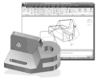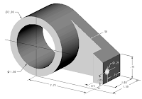
Second Level: 3D Modeling
3D Surface Modeling
Learning Objectives :
* Create 3D surfaces models
* Understand and Apply the different surface modelling Techniques
* Understand the use of 2D SOLID Command
* Understand of use of 3D FACE Command
* Use the hidden EDGE Option
Introduction
As illustrated in the previous chapters, there are no surfaces in a wireframe model; it
consists only of points, lines, and curves that describe the edges of the object. Surface
modeling was developed to provide the surface information that is missing in wireframe
modeling. Essentially, defining the skin of a design creates a surface model. Although it
is possible to create a surface model without using a wireframe model, in most cases it is
much easier to create a surface model on top of a wireframe model. In surface modeling,
a wireframe model can be used to provide information about the edges and corners so
that the desired faces can be easily positioned and placed.
Surface modeling is more sophisticated than wireframe modeling in that surface modelers
define not only the edges of 3D objects, but also the surfaces. Surface modeling provides
hiding, shading, and rendering capabilities that are not available in wireframe modeling.
Surface models do not provide the physical properties that solid models provide, such as
mass, weight, center of gravity, and so on.
The AutoCAD surface modeler defines faceted surfaces using a filled polygon. The
created faces of surface models are only planar, which means the surface models can only
have approximate curved surfaces. It is important to note that the AutoCAD surface
modeler does not create true curved surfaces. To differentiate these two types of surfaces,
faceted surfaces are called meshes in AutoCAD. Because of the use of faceted
approximation on true curved surfaces, the computer requirements of most faceted
surface modelers are typically much less than that of solid modelers. Faceted surface
modeling usually provides reasonably good representations of 3D designs with fast
rendering and shading capabilities. Faceted surface models are also useful for creating
geometry with unusual surface patterns, such as a 3D topographical model of
mountainous terrain.
AutoCAD®2010 provides three basic methods for creating surfaces – the 2D Solid, 3D
Face and Region commands. The three commands were
developed parallel to the
historical development of the different types of computer modelers.
• 2D Solid: The first generation surface command available in AutoCAD. Used
mostly to fill an area in the sketch plane of the current UCS. This type of surface is
not a true 3D surface.
• 3D Face: Creates a true 3D planar surface (allowing X, Y and Z coordinates) of
three-sided or four-sided shape. This is the type of surface developed primarily for
creating faceted surface models.
• Region: Creates a 2D surface of arbitrary shape from existing 2D entities. This
command creates the most flexible and the most complicated type of surface
available in AutoCAD. This command was developed to allow manipulation of 2D
surfaces using one of the solid modeling construction techniques, namely, the
Constructive Solid Geometry method.
Although all three commands
can be used to create planar surfaces, the resulting surfaces
are not equal. In fact, the three commands are developed for specific tasks in mind. The
2D Solid command is mostly used in 2D drawings to create 2D filled area and the
Region command is designed so that general 2D shapes can be easily transformed into
solid models. The 3D Face command is the only one that is designed specifically for
surface modeling and therefore it is the most suitable for such tasks. The use of the 2D
Solid and Region commands in 3D surface modeling can be somewhat awkward and at
times very difficult. Note that the use of the Region command will be focused on in the
solid modeling chapters of this text.
As one can imagine, sketching each surface manually can be very time consuming and
tedious. AutoCAD also provides additional tools for more advanced surface modeling,
such as Tabulated surfaces, Ruled surfaces and Revolved surfaces. These tools are
basically automated procedures, which can be used to define and create multiple copies
of planar surfaces in specific directions. The principles and concepts used by these tools
are also used in creating solid models, which are covered in chapter six through chapter
eight of this text. You are encouraged to re-examine these commands after you have
finished the solid modeling chapters.
In this chapter, the general procedures to create surface models are illustrated. The use of
the 2D Solid and 3D Face commands are illustrated and differences discussed. We will
also demonstrate the use of the more advanced surface modeling tools. Two wireframe
models, which were created in the previous chapters, will be converted into surface
models.
Starting Up AutoCAD® 2010
1. Select the AutoCAD 2010 option on the Program menu or select the AutoCAD
2010 icon on the Desktop.
2. In the AutoCAD Today Startup dialog box, select the Open a Drawing icon with
a single click of the left-mouse-button.
3. Click on the V-block.dwg filename to open the V-block wireframe model that was
created in the previous chapter. (Use the Browse option to locate the file if it is
not displayed.)
• The V-block wireframe model is retrieved and displayed in the graphics window.
The UCS Toolbar and the Meshes Commands
1. In the Menu Bar, select [Tools] [Toolbars] [AutoCAD].
2. Select UCS, with the left-mouse-button, to display the UCS
toolbar on the screen.
The options available in the UCS toolbar allow us to quickly
orient and align the UCS.
3. Click on the Mesh Modeling tab to show the meshes
commands available in AutoCAD.
• Note that a variety of surface modeling commands are
available to create meshes. On your own, move the
cursor on top of the different commands and read the
brief description of the commands.
Creating a Surface Using the 2D Solid Command
The first generation surface command available in AutoCAD was the 2D Solid
command. In AutoCAD 2010, this command can only be accessed through the
command prompt area, which is an indication that this command is slowly being
phased out. The 2D Solid command is used to fill an area in the sketch plane of the
current UCS. It is therefore necessary to properly orient the UCS prior to using the
2D Solid command.
1. Select the 3 Point UCS icon in the UCS
toolbar.
• The 3 Point UCS option allows us to
specify the new X-axis and Y-axis directions
to align the UCS.
2. In the command prompt area, the message “Specify new origin
point<0,0,0>:” is displayed. Pick the lower right corner of
the front face of the wireframe model as shown.


Civil, mechanical and electrical/electronic engineers all use CAD programs but not necessarily the same ones. For example a civil engineer will use AutoCAD however an electrical engineer will use AutoCAD Electrical. An electronics engineer will use OrCAD or similar.
BalasHapusSolidworks Course