4. Inside the arcball, press down the
left-mouse-button and drag it to
rotate the model freely in 3D space.
Observe the display of the shaded
surface in contrast to the 3D
wireframe edges that are located
behind it.
5. In the UCS toolbar, select the World UCS. This
option resets the UCS to align to the world
coordinate system.
6. On your own, reset the display to the SE Isometric
View before continuing to the next section.
Creating a Surface Using the 3D Face Command
• The second generation of surface command made available in AutoCAD was the 3D
Face command. The 3D Face command can be used to create true 3D planar
surfaces by allowing the X, Y and Z coordinates of the corners to be selected
independently of the current UCS. The created polygon can be a three-sided or foursided
shape. This command is the primary construction tool for surface modeling in
AutoCAD.
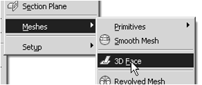
1. In the Menu Bar, select [Draw] [Modeling] [Meshes] [3D Face].

2. In the command prompt area, the
message “_3dface Specify first point or
[invisible]:” is displayed. Pick the lower
right corner of the vertical inclined face
of the model as shown.
3. In the command prompt area, the message
“Specify second point or [invisible]:” is
displayed. Pick the adjacent corner above
the previous selected corner of the vertical
inclined face as shown.
4. In the command prompt area, the
message “Specify third point or
[invisible]:” is displayed. Pick the
adjacent corner of the right vertical
face of the model as shown.
5. In the command prompt area, the message
“Specify fourth point or [invisible] <Create
three-sided face>:” is displayed. Pick the
corner below the last selected corner as shown.
-----------------------------------bersambung--------------------------------------------
Salam Cerca trova - man Jadda wa Jada


Tidak ada komentar:
Posting Komentar