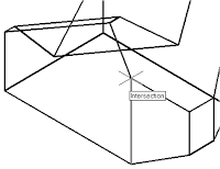
3. In the command prompt area, the message
“Specify point on positive portion of X-axis:”
is displayed. Pick the adjacent corner toward
the right side of the model as shown.

message “Specify point on positive
portion of X-axis:” is displayed. Pick
the right corner of the inclined plane
as shown.
• The new UCS is aligned to the
vertical inclined plane as shown.
Solid to activate the 2D Solid
command as shown
the origin of the new UCS.
7. In the command prompt area, the
message “Specify second point:” is
displayed. Pick the bottom right corner
of the inclined plane as shown.
8. In the command prompt area, the
message “Specify third point:” is
displayed. Pick the corner directly
above the origin of the UCS as
shown.
• The 2D Solid command requires the third point to be specified diagonally opposite to
the second point. This seemly strange way of specifying the third corner was
established when the 2D Solid command was first introduced back in the mid-1980s.
Note that the 3D Face command, the second-generation surface command in
AutoCAD, does not follow this convention.
9. In the command prompt area, the
message “Specify fourth point or
[Exit]:” is displayed. Pick the
corner directly above the second
point we selected as shown in the
figure.
10. Inside the graphics window, rightmouse-
click once to end the 2D
Solid command.
• The 2D Solid command allows the creation of three-sided or four-sided filled
polygons, which can be used to represent faces of surface models. Note that in the
above steps, we could accept the three-sided polygon after defining the third corner.
---------------------------------to be continued---------------------------------------------------


Tidak ada komentar:
Posting Komentar